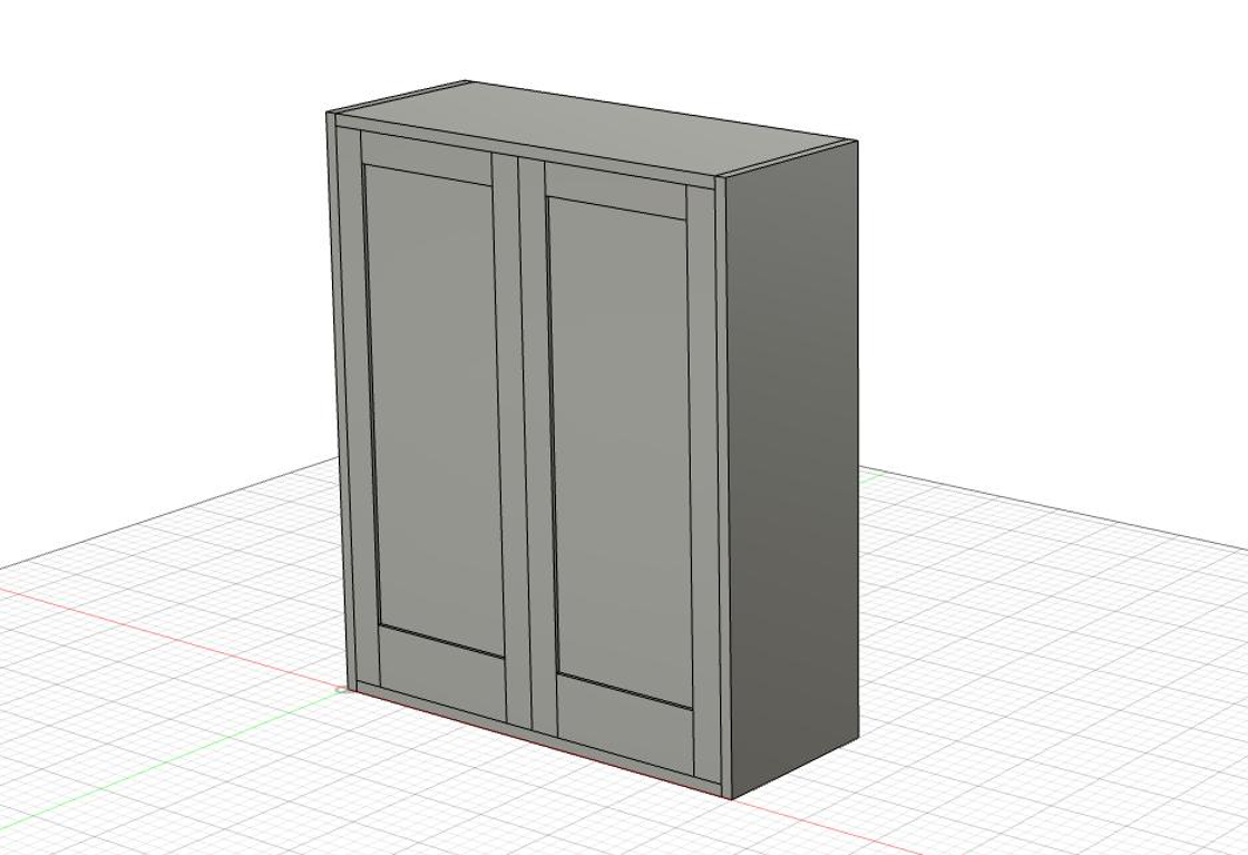
Create a fully parametric wall cabinet with a matched pair of frame-and-panel doors
Now that we have covered the basic concept of a parametric model in episode one of our Fusion 360 in the Woodshop series, it’s time to create an actual piece of furniture. Given its simplicity, a wall cabinet is a great place to start. In this video, you’ll learn how to create a case and turn it into a component, then how to create a pair of matched frame and panel doors—all fully parametric. New tools are covered such as the midpoint-plane tool and the mirror-tool.
Parameters used in this tutorial:
Key commands used in this tutorial
|
Step by step:
Set parameters and make the case
1. Click “Modify”

2. Click “Change Parameters”

3. Click the plus button to add user parameters

4. Height = 36
Width = 30
Depth = 12
CaseThickness = 3/4
StyleWidth = 2

5. Click Ok

6. Create a new sketch.

7. Select the front plane.

8. Create a rectangle from the origin point.
(Key Command = ‘R’)

9. Draw out a rectangle that is (height) X (width)

10. Draw in four lines, starting with the two vertical lines and then the two horizontal lines.

11. Dimension each (CaseThickness) away from the outside rectangle.

12. Select the two vertical segments and extrude them (depth).
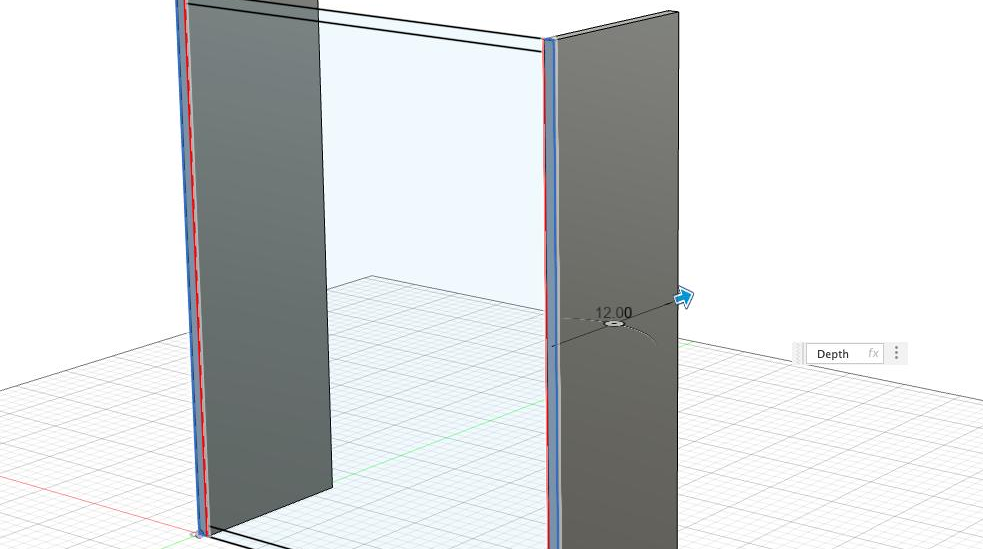
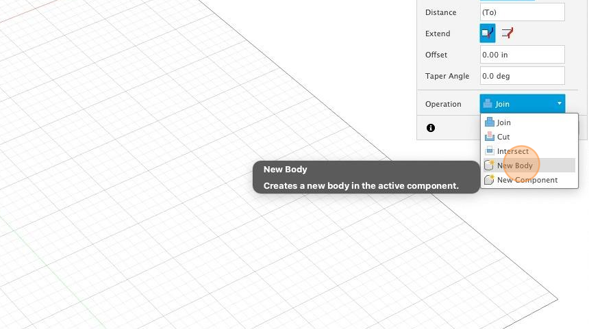
13. Select “New Body” and hit “OK”.
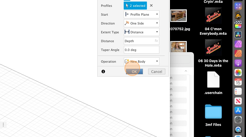
14. Show the sketch again.

15. Extrude the horizontal segments.
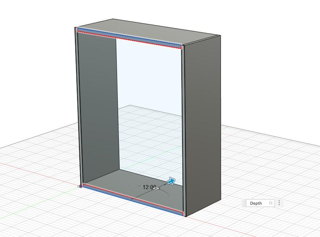
16. Change “Join” to “New Body” and select “OK”.

17. In the browser, right-click on the project and select “New Component”.

18. Name the component and hit “OK”.

19. Select the bodies and drag them into the component.

Create a frame-and-panel door
20. Double-click back into the original sketch.

21. Create a line referencing off the middle of the horizontal. Hover near the middle and when the triangle pops up next to the cursor it snaps to the middle.

22. Draw in the two vertical side styles and the top style. Dimension them to “StyleWidth”.

23. Draw in the bottom style and dimension it (StyleWidth*3).

24. Extrude the vertical styles (CaseThickness).
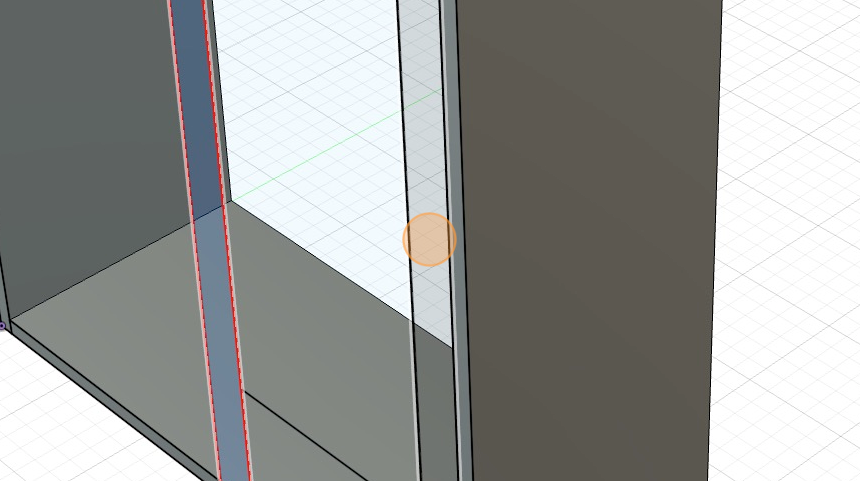
25. Select “New Component” and click “OK”.
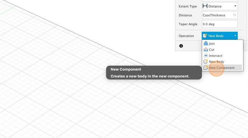
26. Extrude the horizontal styles (CaseThickness).
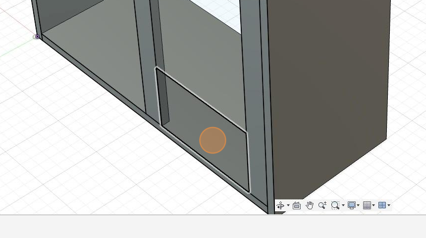
27. Since you just made a new component for the door in step 25, select new body.

Extruding with an offset
28. Make sure that you still have the door component selected.

29. Select the center segment to extrude the panel.

30. Change the start to “Offset”.

31. Set the dimension of the offset to .25 in.

32. Change the extent type to “To Object”
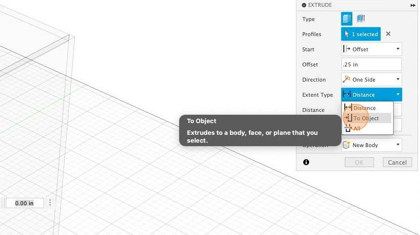
33. Orbit the model to show the back side of the door.

34. Select the back of the frame to set the “To Object” plane.

35. Select a new body and hit “OK”.
Create a mid-point construction plane and mirror the door
36. Select the top project in the browser.

37. In the “Construct” menu select “Midplane”.

38. Select the side as the first plane.
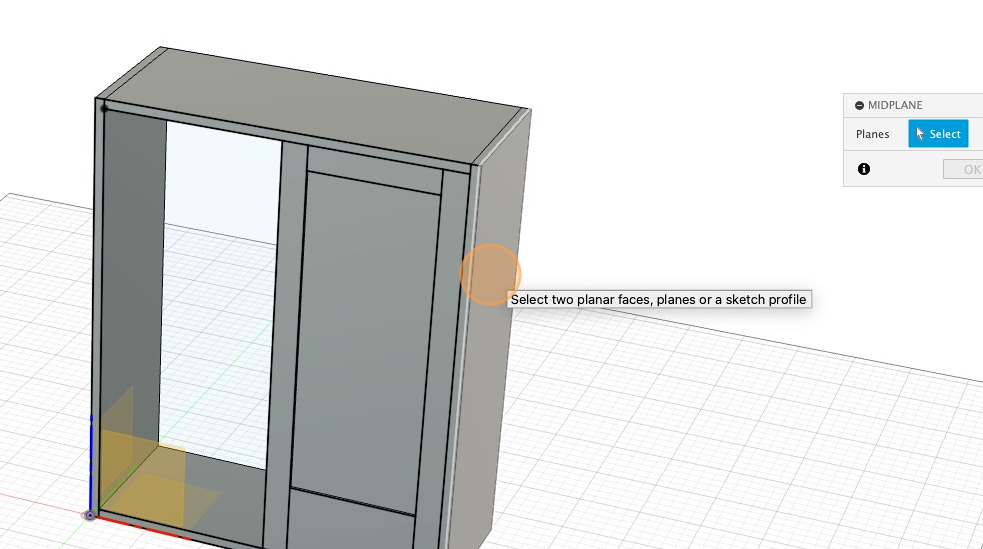
39. Orbit the model to show the opposite side.

40. Select the opposite side as the second plane.

41. Click “OK”. Your midpoint plane is created.
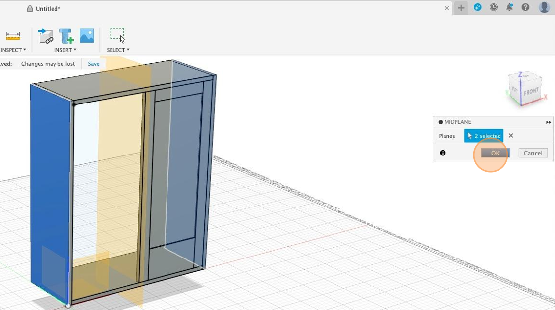
42. In the “Create” menu, select “Mirror”.

43. Change the object type to components.

44. In the browser, select the door you want to mirror.

45. Click on the select option next to mirror plane.

46. Select the midpoint plane.

47. Click “OK”

48. Woot! You’re done.
