If you like to geek out in your woodshop and want to bring Fusion 360 into your workflow, this is the place to start!
Parameters used in this tutorial:
Key commands used in this tutorial
|
Step by step:
If I have known measurements, I prefer to make them into parameters before beginning the modeling. It keeps you from having to go into and out of the Change Parameters menu and allows for a more efficient workflow.
Setting parameters
1. Click “Modify”
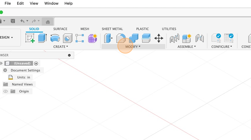
2. Click “Change Parameters”.
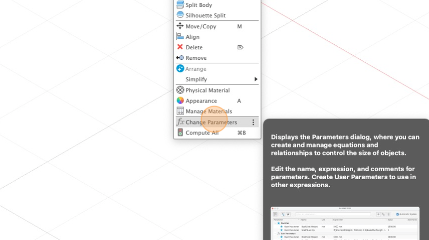
3. Click the “Add User Parameter” button.
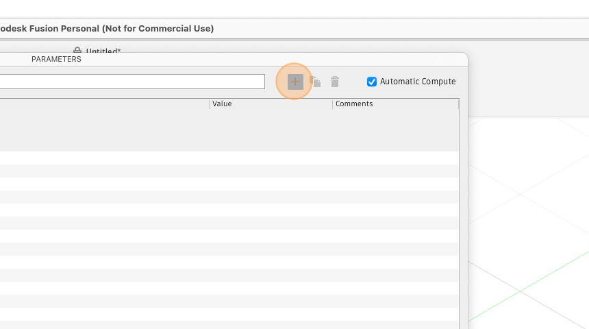
4. Fill in the name (no spaces!) and expression and click ‘ok’.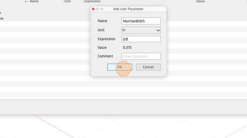
5. Repeat for the rest of the parameters
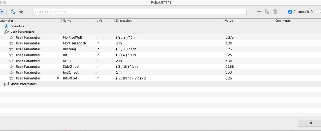
The parameters used in the example are as follows:
• MortiseWidth – 3/8
• MortiseLength – 2
• Bit – 1/4
• Bushing – 3/4
• Meat – 2
• SideOffset – 3/16
• EndOffset – 1
• BitOffset – (Bushing – Bit) / 2
6. Finished parameters
Create the sketch
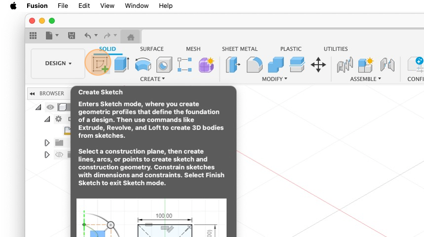
7. Create a new sketch.
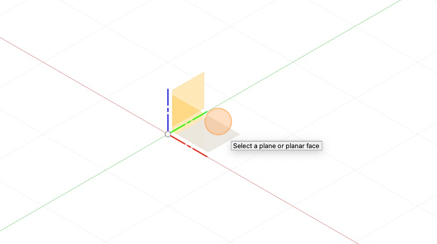
8. Select a plane to draw the sketch on.
9. Type “r” to select the rectangle tool.
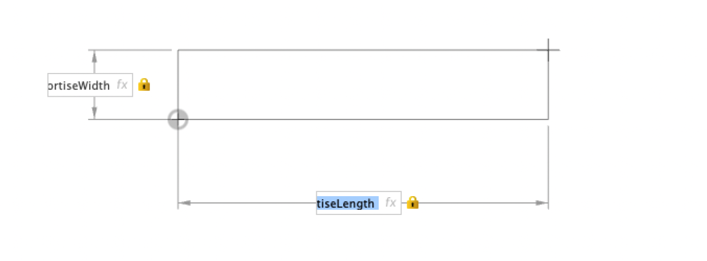
10 Place the first corner on the origin in the center. Draw out a rectangle and type MortiseWidth and MortiseLength in for the sizes. Use the ‘tab’ key to switch between selections.
11. Double-click the side of the rectangle to select the entire rectangle.
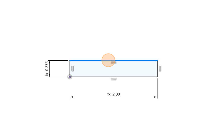
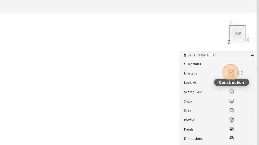
12. Change the line type to construction lines in the Sketch Palette.
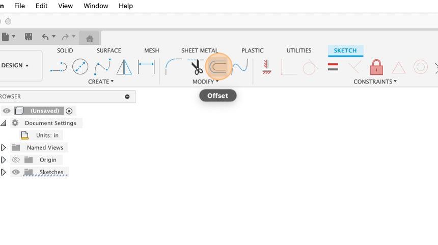
Offset a rectangle to guide the router bushing
13. With the rectangle still selected, click on offset to create a new rectangle offset
Add the base of the template
14. Use the rectangle tool (key command R) to create a new rectangle around the previous two.
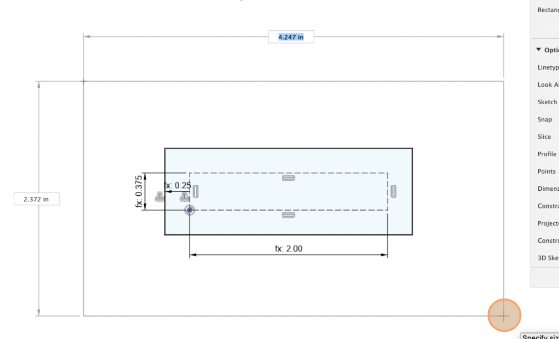
15. Add dimensions using the dimension tool (key command “D”) to all four edges to the outside of the second rectangle. Set the dimensions to “Meat”.
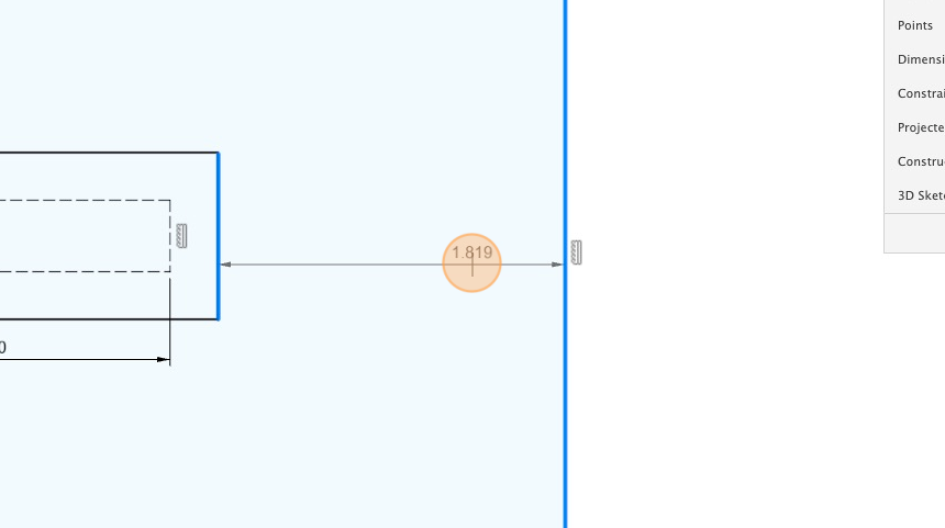
Adding fences stops to the base
16. Select the rectangle tool and click on the edge of the base.
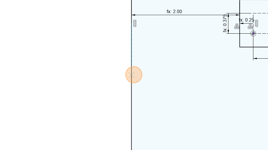
17. Draw out a rectangle to the far edge of the base.

18. Dimension the side fence to .25 inches.
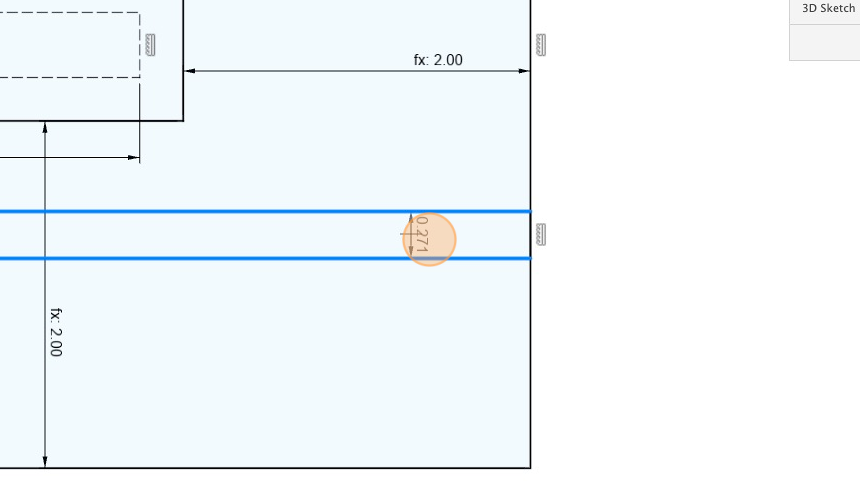
19. Add a second rectangle for the end fence.
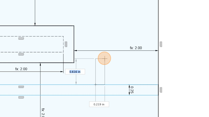
20. Dimension it and select the dimension from the side fence.
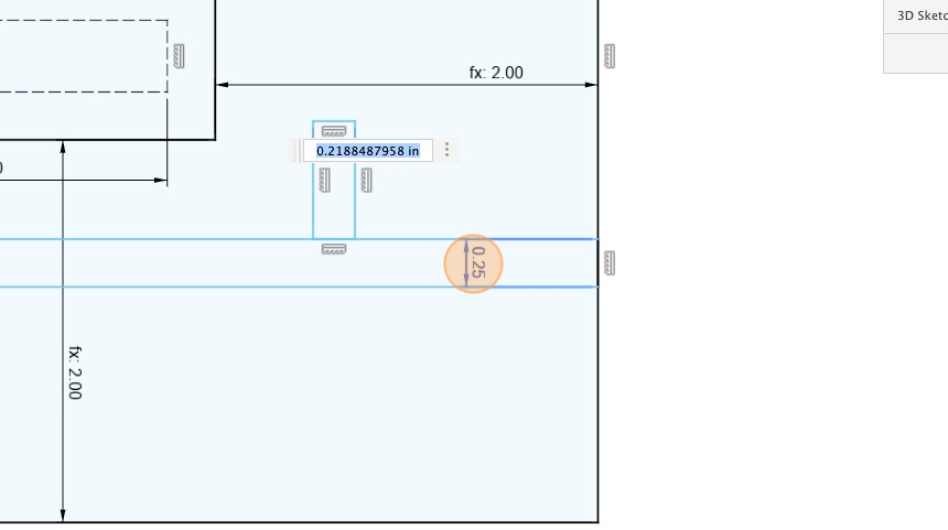
22. Referencing off of the mortise, set the dimension of the side fence to “SideOffset”.
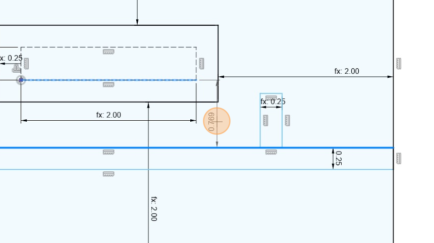
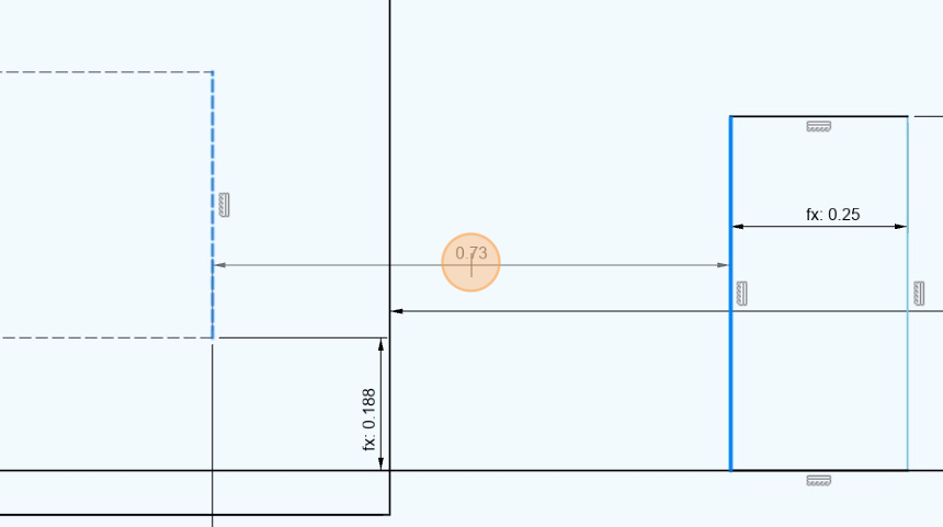
23. Set the dimension of the end fence to “EndOffset”.
24. Your finished sketch should look something like this.
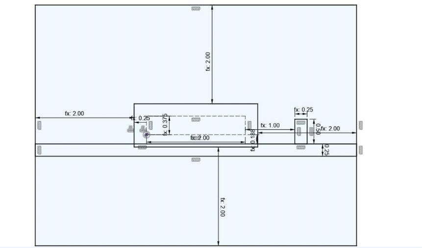
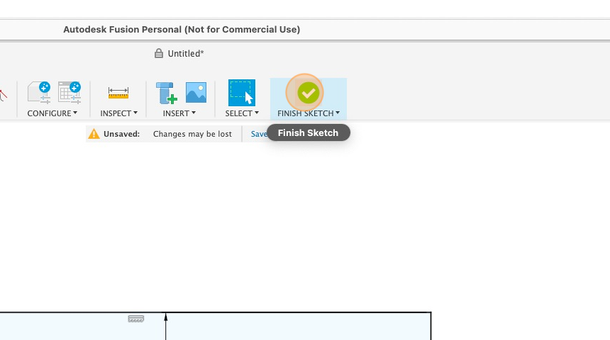
25. Click “Finish Sketch”.
Extruding out the template
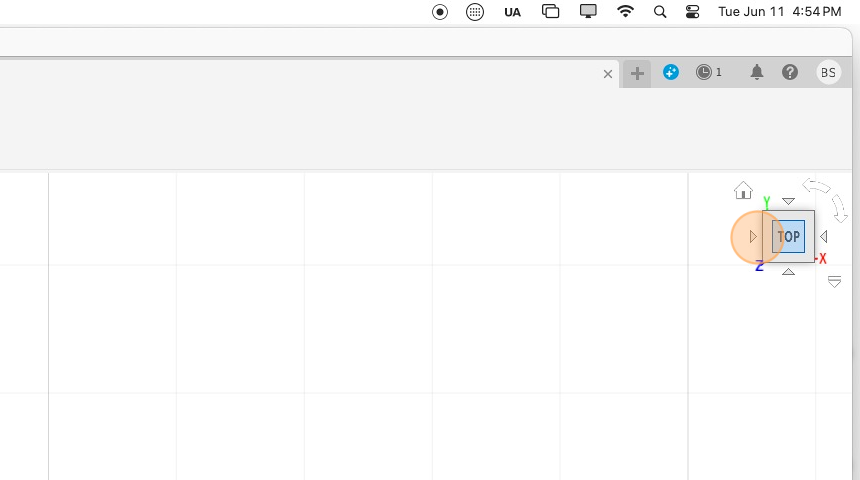
26. Use the orbiter to move the view.
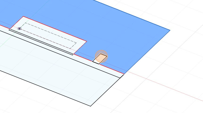
27. Holding down “shift”, select all of the segments to extrude.
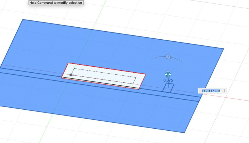
28. Using the extrude tool (key command “E”), extrude the selection 3/8 of an inch.
29. Orbit until you can see the bottom of the body you just created.
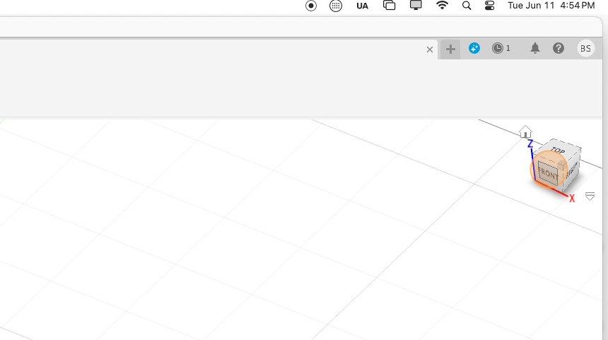
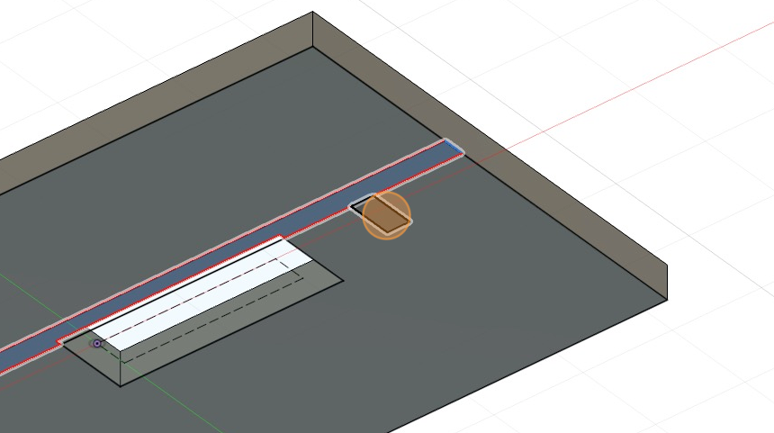
30. Show the sketch again in the browser and extrude the two fences out -1 inch.
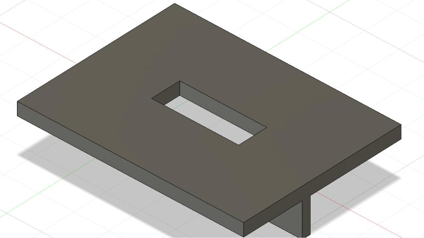
31. You have created a parametric mortising template!


Ben, thanks for doing this. Wanted to learn Fusion 360 but as a woodworker. This is very helpfu.